The Opportunity for Water Reuse at Battery Gigafactories
A Gresham Smith project engineer details ways water reuse can reduce carbon footprint at EV battery production facilities.

At a Glance
- The need for more EV factories is growing at the same time as sustainability and carbon-footprint concerns.
- New battery facilities can have water demands in the millions of gallons per day.
- Water reuse strategies can reduce water demand, environmental stress, and carbon footprint.
As major automakers pivot to electric vehicles (EVs), construction of new lithium-ion battery production facilities has exploded throughout North America. Carmakers and their technology partners are investing $500 billion by 2026 to fortify their supply chains and factories. What’s also unprecedented is the size and scope of these facilities. Many are multibillion dollar investments in multimillion square-foot facilities that have a significant impact on local utility providers, specifically power and water. In addition, these facilities are often built in small (think 250,000 or fewer residents) rural communities with limited utility infrastructure, which compounds the challenges associated with building and operating them.
A new battery facility can have water demands in the millions of gallons per day (MGD), a potentially disproportionate demand compared to the per capita demand of the communities they may be built in. Available data suggests that the average water demand for these facilities is approximately 28% of the current daily domestic water demand of the service areas where the plants are being built.
At the same time the transition to EVs is taking place, these same automakers are also pursuing sustainability goals and net zero carbon futures, which require them to look at the cost of doing business and the resulting local and global carbon footprints. While much of the focus has been on the rapid shift and investment in EVs, it’s also important to consider how these global companies will be able to meet their net zero goals while building these massive facilities across North America.
In this article, I’ll explain how water reuse strategies should be top of mind for automakers as they build and retool these facilities. There are a number of ways to approach this outcome, and each has varying effect on carbon and water impact.
Background and methodology
To understand how these potential water reuse scenarios can be implemented into EV battery production facilities to reduce their water demand and carbon footprint, we first need to understand how water factors into the battery production process.
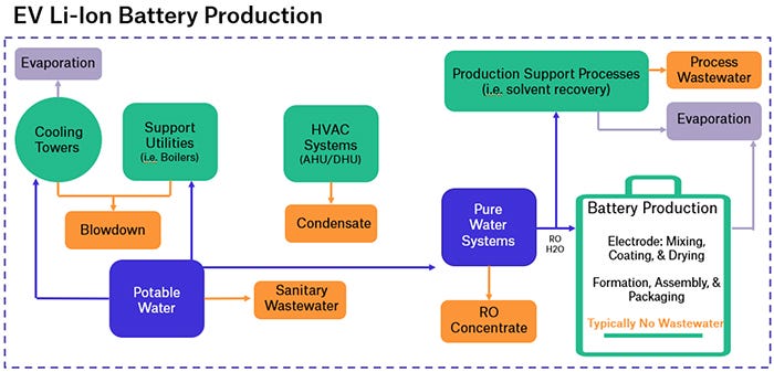
Production diagram. Credit: Gresham Smith
Typically, about 50% of the water from the battery production process is evaporated, a third is discharged as wastewater and the rest is used up in the production process. Cooling towers generate the majority of the water demand, and that’s where we focused our efforts on determining the best reuse scenarios for replacing that water demand. In addition to the reuse capture benefit, higher quality treated reuse water can allow for more efficient cooling tower operations further reducing overall facility water demand. The included graphics illustrate the process.
Suitable water reuse sources at typical battery production facilities were identified by reviewing available high quality wastewater sources as well as other potential reuse water capture opportunities such as site stormwater collection and cooling tower plume capture. Next, these potential sources were characterized by available flow rates and matched to the potable water demands of the facility to confirm flow and water quality compatibility.
We then determined conveyance and treatment requirements for water reuse scenarios to meet potable water demands. New and innovative technologies were reviewed to maximize reuse possibilities.
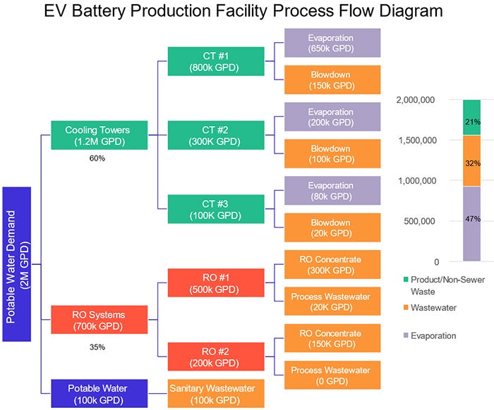
Process flow diagram. Credit: Gresham Smith
We then developed concept planning-level direct and indirect costs for the implementation of each reuse scenario. For direct costs, these included capital, operations and maintenance (O&M), engineering and life cycle costs. Indirect costs included operational and embodied carbon impacts of implementation and their resiliency impacts. The carbon footprint of each scenario was calculated using a life cycle assessment to find the resulting greenhouse gas emissions.
Finally, the return on investment (ROI) was evaluated based on the resulting direct cost payback periods, indirect costs as represented by carbon footprint, and resiliency factors, in comparison with the baseline scenario of direct purchase of public water and sewer services.
Four water reuse scenarios
Several variations of the collection, treatment and reuse of water collected at battery production facilities to supplement make-up water demand of cooling towers were evaluated. In addition to producing a reuse water source, the resulting quality of the treated wastewater improves the efficiency of the cooling towers therefore potentially reducing overall water demand by a significant margin.
At a representative facility, annual water demand totaled 440 million gallons (MG), of which nearly 220 MG are discharged as wastewater, 132 MG are evaporated and the remainder is used up in production. Each scenario evaluated reducing the volume discharged or lost to the environment as well as reducing overall demand by improving operational efficiency.
Here’s a deeper look at four scenarios, each with their own costs, benefits and return on investment.
Blowdown and RO concentrate
Collecting and treating all blowdown and reverse osmosis (RO) concentrate sources throughout the facility results in annual average reuse production of an estimated 25MG. By supplementing potable water with high quality permeate produced by this reuse scenario, the available cooling tower cycles increase thereby decreasing water demand by 50 MG. In total, this option offsets 75 MG or 17% of total facility demand.

Gresham Smith Project Engineer Diana Chumak. Credit: Gresham Smith
At the representative facility, construction was well underway. Therefore the addition of treatment equipment and piping resulted in a payback period of 15 years due to significant design additions and modifications from space constraints. Integration of this option into the initial design phases can significantly reduce costs and the payback period. The net annual emissions of implementing this reuse option are 800 pounds (lbs) of carbon dioxide equivalent (CO2e) per MG of reuse produced per year, for an assumed 15 year operational lifetime.
Takeaway: This scenario offers a 15-year payback period and low annual greenhouse gas emissions; however, the payback period could be significantly reduced if design of this option were integrated into the front end of the project. The consistency, large volume and high quality nature of this reuse option also improves overall efficiency and resiliency for the facility.
Stormwater capture
Stormwater capture consists of collecting and treating rooftop runoff from the main production facility. The surface area of the facility roof totaled 2 million square feet and drained to either side of the building, identified as the east and west sides. An underground collection tank and treatment system was evaluated on either side of the building with the treated reuse water intended to be used as a supplement to the cooling towers. We created a model to integrate precipitation probability, frequency, and intensity factors with the seasonal demand of cooling towers to optimize tank sizing.
A 600,000 gallon tank on the east side collected a larger portion of the rooftop runoff which resulted in the lowest payback period and annual emissions of the two sides. The stormwater captured by the east side tank offset water demand by 31 MG per year. Additionally, the lower pH of stormwater relative to the municipal water supply allows for improved cooling tower efficiency by diluting the highly alkaline potable water source. By improving efficiency, an additional 45 MG of water is offset. Implementing a stormwater capture system totals to 76 MG offset annually or 17% of total facility water demand. The resulting payback period is 4 years and net neutral carbon emissions.
Takeaway: This option results in net neutral annual emissions with a payback period of 4 years. Stormwater capture presents an opportunity to significantly reduce water intensity without increasing carbon emissions.
Plume capture
Plume capture is the reuse of the evaporation from cooling towers using electrically charged collector mechanisms to attract and collect water droplets to supplement make-up water demand for cooling towers. This process requires using a specialized vendor, and the main costs are from the equipment itself, as this option does not require significant pumping or conveyance.
The collected water is of distilled quality, meaning it improves cooling tower operation and efficiency. Direct capture of the plume results in 9 MG of reuse flow and the improvement in cooling tower operation results in an additional 24 MG of demand reduction, totaling to an annual offset of 33 MG or 7% of total facility demand. Installing this option results in a payback period of 6 years and net annual emissions of 5,100 lbs CO2e per MG. The high emissions stem from the amount of electricity required to charge the collector mechanisms and condense the plume. This innovative reuse option produces a winter based seasonal reuse stream that can be paired with another reuse stream to improve overall facility resiliency.
Takeaway: While this option does require engaging a specialized vendor, the primary cost comes from the equipment itself, and the payback period is 6 years. In addition, this approach can easily be retrofitted to any existing facility. In a facility with access to renewable energy, the emissions from electricity usage can be significantly mitigated.
Condensate collection
Battery production facilities require extensive HVAC systems to maintain specific operational conditions, including dehumidification and air handling units (DHUs/AHUs). Collecting condensate produced by these units throughout the main battery production facility resulted in an estimated water reuse production of 9 MG annually. Direct costs and savings from implementation lead to a payback period of 34 years, due to multiple DHU/AHU sources across the facility and the resulting need for extensive condensate collection and conveyance infrastructure. As with other options, approaches to integrate condensate collection into the initial facility planning and design could decrease overall cost and payback period. The greenhouse gas emissions resulted in an increase of 14,000 lb CO2e per MG annually.
Takeaway: This option is generally only recommended for new facilities if the condensate can be collected via gravity to lower direct and indirect costs. Also, in terms of water resiliency, this option provides a consistent high quality wastewater stream for reuse during peak temperature conditions, which may be particularly useful during potential drought periods.
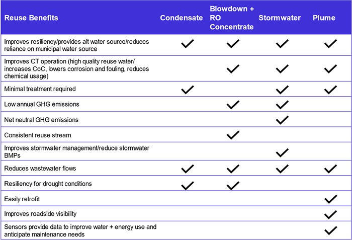
This chart shows a breakdown of the reuse benefits of each scenario. Credit: Gresham Smith
Implementing water reuse at battery production plants as well as other industrial facilities with large water demands helps achieve sustainability goals and reduce impacts on local water and wastewater utilities. Viable solutions at the representative facility for reducing water intensity while limiting carbon emissions include the collection and treatment of stormwater or blowdown and RO concentrate. Multiple reuse scenarios can even be paired based on seasonal production to reinforce resiliency. These and other solutions can be customized to new or existing facilities based on total water demand, available reuse volume and quality, as well as opportunities to improve operational efficiency and reduce overall demand.
About the Author(s)
You May Also Like


